
Vector Magnetic Field Systems for Multi-Axis Field Control
Generate controlled magnetic fields across multiple axes for direction-dependent measurements, anisotropy studies and spintronic experiments.
Designed for projects where field direction, axis coordination and sample orientation are as important as field strength.
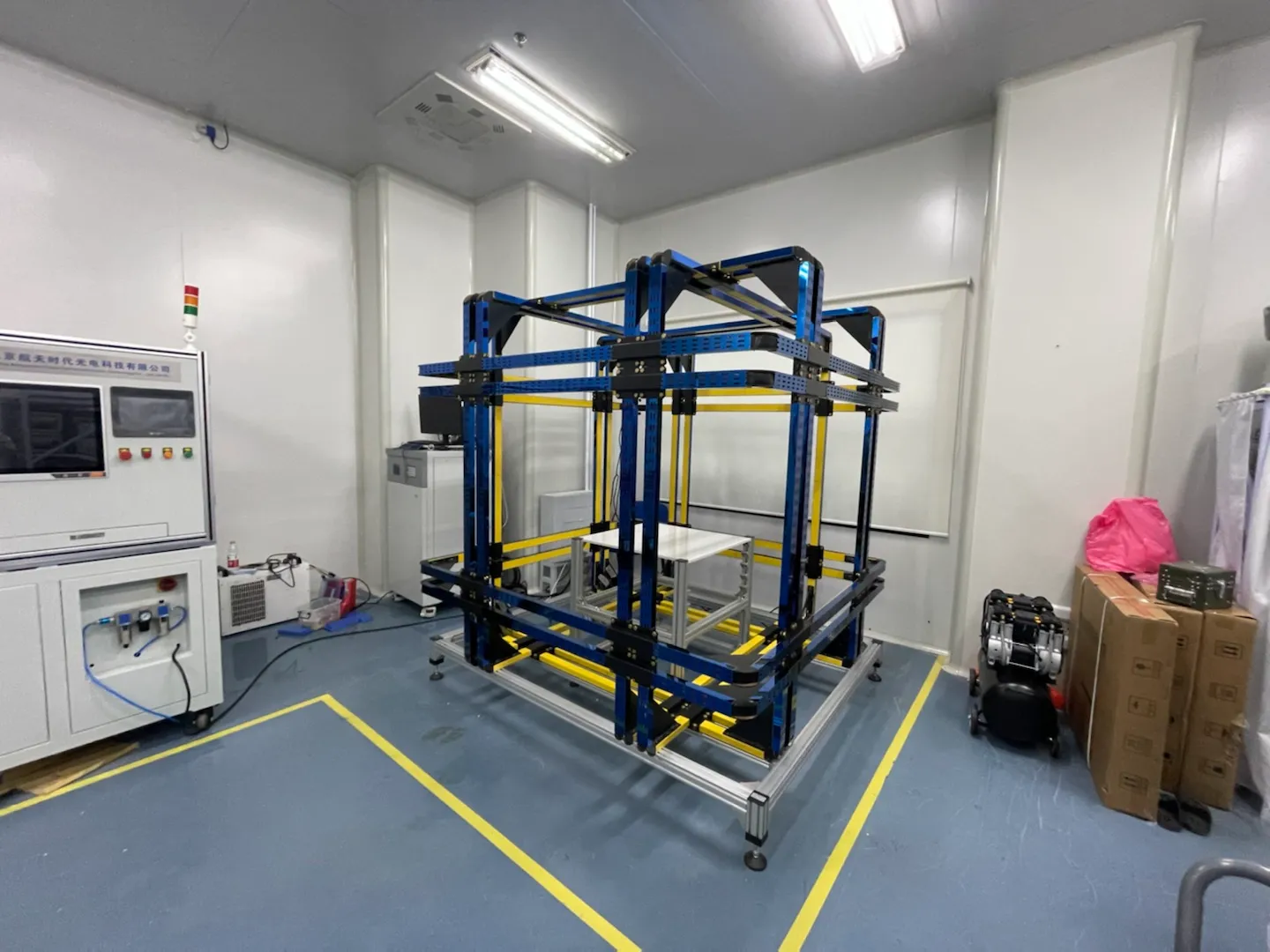
Multi-axis field control
X, Y and Z field components
Vector field workflow
direction, rotation, sequence
Sample orientation
access, stage, wiring path
Field direction control
Define the magnetic-field direction, rotation path or angular sequence required by the experiment.
Multi-axis coordination
Match magnet structure, current channels and software control for two-axis or three-axis operation.
Application-specific access
Keep the sample, holder, probes and cables compatible with the required field directions.
Start with the required field direction, axis count, target field and sample orientation.
Contact usConfirm the Conditions Behind a Vector Field System
A vector magnetic field system should be defined by field direction, axis count, per-axis field targets and the way the sample will be positioned during measurement.
Selection logic
Vector-field performance depends on axis coordination, current synchronization, sample orientation and how the combined field will be verified.
Field vector requirement
Confirm: required field direction, vector path, angular sequence or fixed orientation
Why: The field vector defines how each axis must work together during the experiment.
Axis count
Confirm: two-axis, three-axis or custom multi-axis field control
Why: Axis count determines magnet geometry, current channels, control logic and calibration work.
Target field per axis
Confirm: field range, polarity, resolution and operating mode for each axis
Why: Each axis may require different current capacity, cooling design and protection limits.
Direction and rotation
Confirm: static direction, angular scan, rotation path or field reversal sequence
Why: Direction control affects software commands, sweep timing, data matching and repeatability.
Working volume
Confirm: sample position, uniform region, tolerance and available clearance
Why: Vector-field accuracy only matters at the actual sample position and measurement region.
Sample orientation
Confirm: sample holder, rotation stage, probe access, cables and wiring path
Why: The sample layout must remain compatible with all required field directions.
Power synchronization
Confirm: current stability, channel matching, ripple, control interface and timing
Why: A vector field depends on synchronized current output across multiple axes.
Cooling and duty cycle
Confirm: heat load, operating time, cooling method and protection requirements
Why: Long vector sweeps or multi-axis loading can increase thermal drift and system limits.
Send the known field direction, axis count, target field and sample orientation first.
Start Vector Field ReviewCoordinate the Modules Behind Multi-Axis Magnetic Fields
A vector magnetic field system combines magnet geometry, synchronized power channels, control software and sample access into one direction-controlled field workflow.
Multi-axis magnet structure
X, Y, Z geometry and working space
Power channels
current range, matching, stability
Vector control software
direction, rotation, sweep sequence
Sample stage
orientation, holder, probe access
Field sensing
mapping, alignment, vector check
Cooling and protection
heat load, duty cycle, interlocks
Define field vector
Start from direction, angle path and axis count.
Match power channels
Check current range, timing and synchronization.
Plan sample access
Keep holder, probes and cables clear for all axes.
Verify combined field
Review axis alignment and vector-field behavior.
A vector field system should be configured around direction control, not only field strength.
Discuss System ModulesChoose the Vector Field Configuration That Fits the Measurement Path
Different vector field layouts support different axis counts, field ranges, sample access needs and direction-control workflows.
Two-Axis Vector Field System
For in-plane field rotation, angular response studies and direction-dependent measurements across two controlled axes.
Used for: planar anisotropy, angular scans and two-axis magnetic response testing
Three-Axis Vector Field System
For full vector-field control where X, Y and Z components must be coordinated around the sample position.
Used for: vector rotation, 3D field paths and multi-axis spintronic experiments
Vector Electromagnet System
For projects that need stronger field output with controlled direction and defined sample access.
Used for: higher-field anisotropy studies, magnetic materials and transport experiments
Vector Coil System
For lower-field direction control, larger working regions or compensation-style vector-field workflows.
Used for: low-field vector control, sensor work and background-field compensation
Cryogenic Vector Field Configuration
For low-temperature experiments where vector-field direction, sample wiring, cryostat access and thermal constraints must be considered together.
Used for: cryogenic transport, spintronics and direction-dependent low-temperature measurements
Configuration depends on vector behavior.
The right layout is defined by field direction, axis count, per-axis field target, sample access and how the combined field is controlled.
Confirm before selecting
If the configuration is uncertain, start from the field-direction workflow and sample layout.
Discuss Vector ConfigurationVerify the Vector Field Before Direction-Dependent Testing
Testing should confirm axis alignment, combined-field behavior, channel synchronization and sample-position conditions required by the measurement path.
Vector field test flow
Project conditions define how each axis and the combined vector field should be checked.
Axis alignment
Confirm X, Y and Z direction references around the sample position.
Per-axis output
Check current range, field response and protection limits for each axis.
Combined field
Verify vector direction, field rotation path and axis coordination.
Sample layout
Review holder, stage, probe clearance and wiring under field-direction changes.
Acceptance record
Prepare axis notes, vector checks and project-specific handover records.
Verification items
Axis alignment verification
Covers: axis direction, coordinate reference, sample center and installation position
Record: axis alignment note / reference diagram
Per-axis field check
Covers: field range, polarity, response, protection and repeatability per axis
Record: single-axis field note / channel check
Vector accuracy review
Covers: combined-field direction, angle path, rotation sequence and vector error
Record: vector field review / mapping note
Power synchronization
Covers: channel timing, ripple, current matching, sweep control and communication
Record: power channel check / control note
Sample access review
Covers: sample holder, rotation stage, probe access, cable path and clearance
Record: layout review / interface confirmation
Thermal and protection check
Covers: heat load, cooling method, duty cycle, interlocks and shutdown logic
Record: cooling and safety checklist
Testing note
Do not treat separate single-axis checks as proof of vector-field performance. The combined field path and sample-position conditions should also be reviewed.
Confirm axis behavior and combined-field control before treating the system as ready.
Discuss Testing RequirementsSend a Vector Field Requirement for Engineering Review
Start with the required field direction, axis count, per-axis target field and sample layout. The vector-field configuration can be reviewed before a fixed system is selected.
What to prepare
A clear inquiry should describe the field-direction workflow, not only the maximum magnetic field.
Inquiry review path
Known values can be submitted first. Axis details, sweep logic and testing records can be clarified before quotation or detailed design.
Field path
direction, axis, angle
Configuration
magnet, power, access
Review
sync, test, handover
Vector field inquiry form
Use this form structure to collect the engineering inputs needed for a multi-axis field-control review.
Submit the known field path first. The engineering review can complete the missing axis details.
Contact Engineering Team