
Helmholtz Coils for Uniform Magnetic-Field Generation
Generate defined uniform-field regions for calibration, compensation, sensor testing and laboratory magnetic-field control.
Designed for projects where field uniformity, working volume and axis control matter more than maximum field strength alone.
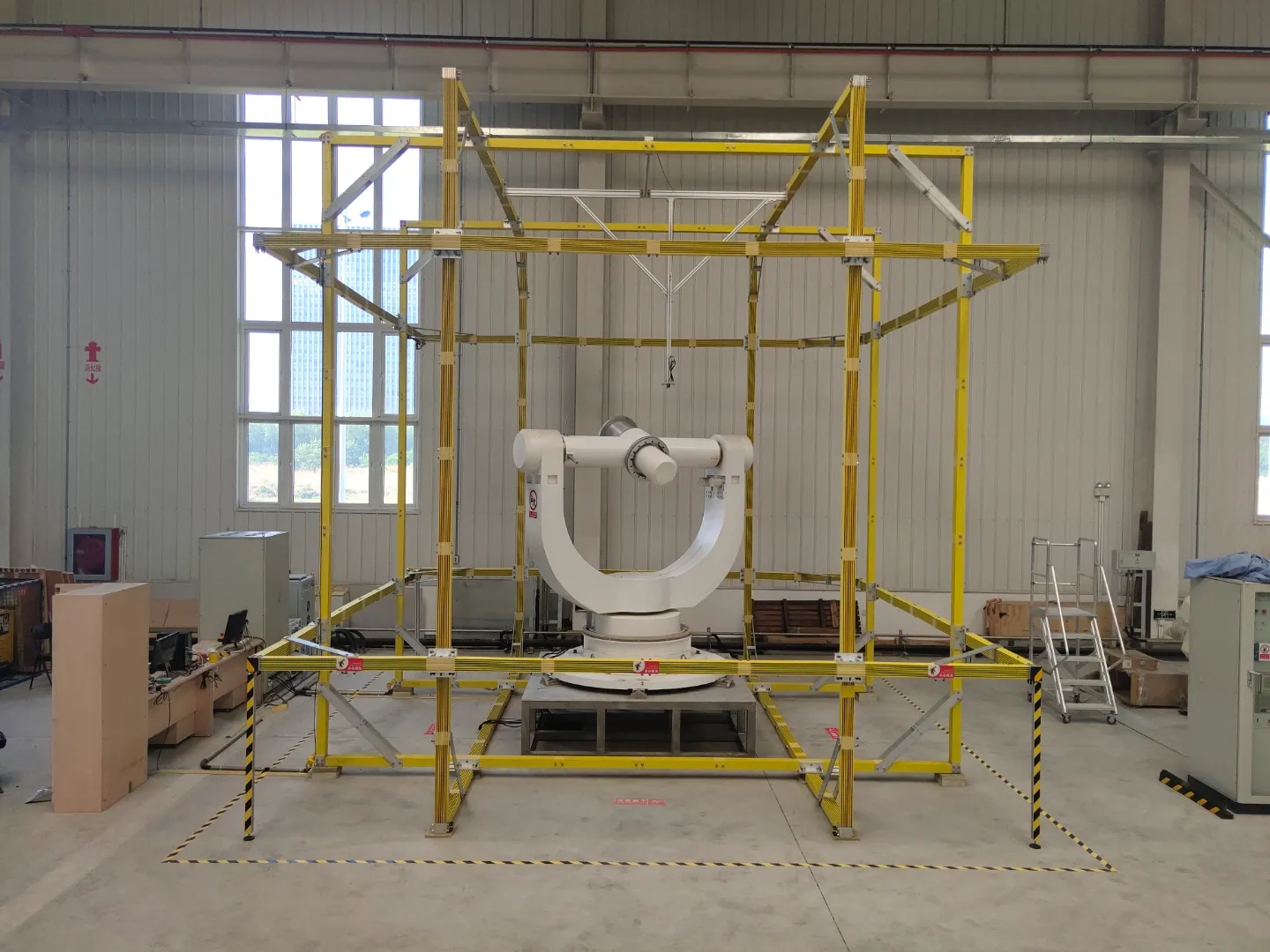
Uniform field volume
defined working region
Coil geometry
diameter, spacing, axis
Current source
stability and control
Uniform field region
Define the working volume where field uniformity must be maintained for the sample, probe or device under test.
Axis and field direction
Choose single-axis or three-axis layouts according to field direction, compensation needs and test workflow.
Calibration-ready setup
Support field mapping, current stability review and project-specific acceptance records when required.
Start with the required uniform region, target field and axis direction.
Contact usConfirm the Conditions Behind a Uniform-Field Coil System
A Helmholtz coil requirement should define the usable field volume, target field, axis direction and operating conditions before coil geometry is fixed.
Selection logic
Uniform-field performance depends on geometry, current stability, sample access and how the field will be verified.
Uniform field volume
Confirm: required working volume, uniformity tolerance and measurement position
Why: The useful field is the region where uniformity is maintained, not the outer size of the coil frame.
Target magnetic field
Confirm: field range, polarity, resolution and static or swept operation
Why: The field target affects coil turns, current source range, heat load and achievable stability.
Axis count
Confirm: single-axis, two-axis or three-axis field control
Why: Axis count determines coil structure, control channels, calibration method and installation space.
Field direction
Confirm: horizontal, vertical or vector direction relative to the sample
Why: Field direction affects sample mounting, probe access, wiring layout and measurement repeatability.
Sample or device size
Confirm: sample envelope, holder size, cables and clearance
Why: The object under test must fit inside the usable uniform region with enough access for operation.
Coil diameter and spacing
Confirm: available space, frame limits and required working distance
Why: Geometry sets the relationship between field uniformity, access, mechanical size and current demand.
Power and control
Confirm: current stability, ripple, control mode and communication interface
Why: A uniform coil system depends on stable current and controlled operation, especially during calibration.
Cooling and duty cycle
Confirm: air or water cooling, operating time, heat rise and installation environment
Why: Thermal drift can change resistance, current demand and long-duration field stability.
Send the known uniform region, target field, axis direction and sample size first.
Start Coil Configuration ReviewBuild the Coil System Around the Required Uniform Field
A Helmholtz coil system combines coil geometry, stable current supply, field verification and mechanical access into one configured field-control path.
Coil geometry
diameter, spacing, axis layout
Current source
range, stability, control mode
Field verification
probe access, mapping, calibration note
Sample interface
fixture, clearance, wiring path
Cooling layout
air, water, heat rise, duty cycle
Control and safety
software, interlocks, operating limits
Start from field volume
Define the usable region before selecting coil size.
Match current source
Check current range, ripple and control requirements.
Plan access and fixtures
Keep sample, probe and wiring inside the working layout.
Verify before delivery
Use field mapping or project records when required.
A useful Helmholtz coil system is configured around the field region, not only the coil pair.
Discuss System ModulesChoose the Coil Configuration That Matches the Field Task
Different Helmholtz coil layouts support different field directions, working volumes, calibration workflows and compensation requirements.
Single-Axis Helmholtz Coils
For generating a defined uniform field along one direction in a controlled working region.
Used for: sensor checks, sample exposure and basic field-control experiments
Three-Axis Helmholtz Coils
For vector field control, directional testing and compensation where field direction changes during the workflow.
Used for: magnetic compensation, orientation studies and multi-axis calibration
Large-Aperture Coil Systems
For larger devices, assemblies or test spaces that need access inside a uniform-field region.
Used for: equipment testing, component validation and large working volumes
Calibration and Sensor Test Systems
For repeatable magnetic-field conditions with current control, probe access and optional field mapping.
Used for: magnetic sensors, probes, meters and compass-related devices
Field Compensation Systems
For reducing background magnetic-field influence or creating a controlled low-field environment around the test object.
Used for: background cancellation, low-field experiments and environmental field control
Configuration is not only coil size.
The right configuration depends on the usable field volume, axis direction, current stability, installation space and how the field will be verified.
Confirm before selecting
If the configuration is uncertain, start from the field task and working volume.
Discuss Coil ConfigurationVerify the Uniform Field Before the Coil System Is Accepted
Testing should confirm the useful field region, axis behavior, current stability and operating conditions required by the application.
Helmholtz coil test flow
Project conditions define what should be checked before delivery or acceptance.
Field volume
Confirm the usable region and the position where field uniformity matters.
Axis behavior
Check field direction, single-axis or three-axis operation and alignment needs.
Current stability
Review current range, ripple, control response and operating repeatability.
Thermal operation
Check heating, duty cycle and cooling method under expected use conditions.
Acceptance record
Prepare mapping notes, test items and project-specific handover records.
Verification items
Field uniformity mapping
Covers: working volume, tolerance, center position and probe path
Record: field map or uniformity note when required
Axis alignment check
Covers: field direction, coil axis, sample orientation and multi-axis layout
Record: axis review / installation reference
Power stability review
Covers: current range, ripple, resolution, control mode and communication
Record: current source check / control note
Cooling and heat rise
Covers: air or water cooling, operating time, duty cycle and temperature rise
Record: cooling check / operating condition note
Fixture and access review
Covers: sample holder, probe clearance, wiring path and installation space
Record: layout review / interface confirmation
Acceptance documents
Covers: agreed test items, buyer notes, packing checks and handover details
Record: FAT checklist / project-specific record
Testing note
A generic checklist is not enough. The test scope should follow the field volume, axis count, duty cycle and verification method agreed for the project.
Confirm the field region and verification method before treating the system as ready.
Discuss Testing RequirementsSend a Helmholtz Coil Requirement for Engineering Review
Start with the field region, target field, axis direction and sample conditions. The coil configuration can be reviewed before a fixed model is selected.
What to prepare
A clear inquiry does not need every detail, but it should define the conditions that shape the coil geometry and verification plan.
Inquiry review path
Known values can be submitted first. Missing conditions can be clarified before quotation or detailed design.
Conditions
field, volume, axis
Configuration
coil, current, access
Review
testing and handover
Helmholtz coil inquiry form
Use this form structure to collect the engineering inputs needed for a uniform-field coil review.
Submit the known conditions first. The engineering review can complete the missing items.
Contact Engineering Team