
Research Electromagnets for Controlled Magnetic-Field Experiments
Configure electromagnet systems by field range, pole gap, uniformity, sweep mode, cooling and sample access. Magverge supports research and industrial R&D projects where the magnet, power supply, fixtures and measurement path must work as one system.
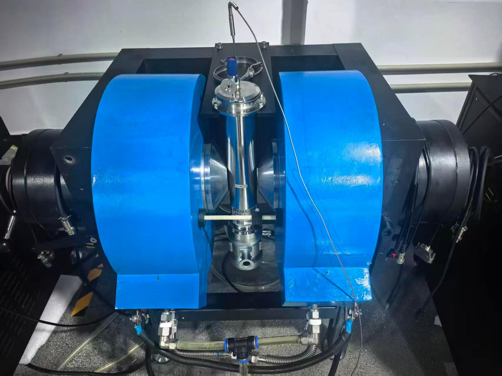 Field source
Electromagnet system path
Best for
Controlled DC or swept magnetic fields for material testing, sensor evaluation and field-dependent measurements.
Review first
Target field, pole gap, uniformity, sweep mode, sample access, cooling method and power stability.
Matched modules
Electromagnet, magnet power supply, fixtures, cooling, safety protection and measurement interfaces.
Not just a magnet
The page should lead buyers toward a configuration review instead of forcing a fixed model too early.
Define the Conditions Before Choosing an Electromagnet
An electromagnet system should be reviewed by experiment conditions before a model is selected. Field target, pole gap, uniformity, sweep behavior, cooling and sample access determine the magnet structure and the matched power supply.
Minimum details for review
These inputs are enough to begin a useful configuration discussion.
Target magnetic field
Confirm: field strength, polarity, sweep range and field profile
Why it matters: The field target defines magnet size, excitation current, cooling demand and power supply range.
Pole gap
Confirm: gap distance, working space and sample clearance
Why it matters: Pole gap affects reachable field strength, field uniformity and whether the sample or fixture can be installed.
Field uniformity
Confirm: uniform area, tolerance and measurement position
Why it matters: Uniformity determines whether the field is suitable for calibration, sensor testing or repeatable material measurement.
Sweep mode
Confirm: DC hold, field sweep, reversal, step mode or cycling
Why it matters: Sweep behavior affects power supply control, heat load, protection logic and data repeatability.
Cooling method
Confirm: air cooling, water cooling, duty cycle and operating time
Why it matters: Cooling limits continuous operation, field stability and practical laboratory installation.
Sample access
Confirm: sample size, holder, probe, wiring and movement path
Why it matters: The magnetic field is useful only when the sample can be mounted, wired and positioned correctly.
Power stability
Confirm: current stability, ripple, resolution and protection
Why it matters: Measurement quality depends on how well the power supply is matched to the magnet load and test sequence.
Selection note
If one condition is uncertain, send the known values first. Missing items can be reviewed before quotation or detailed design.
Send the known field, pole gap, sample access and measurement method first.
Start Configuration ReviewMatch the Magnet, Power Supply and Interfaces as One System
An electromagnet project should be reviewed as a working measurement chain. The magnet geometry, power supply, cooling method, fixtures, safety logic and measurement interfaces must be matched before quotation or detailed design.
Electromagnet system chain
Each module should support the same field target, sample geometry and measurement workflow.
Magnet geometry
pole gap, field target, uniformity
Power supply
current range, stability, sweep
Cooling layout
air, water, duty cycle
Measurement interface
sample wiring and data path
Fixtures & safety
sample holder, protection, interlocks
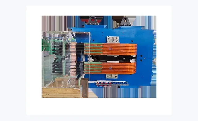
Electromagnet body
Defines field range, pole gap, pole face, magnetic geometry and working space.
Magnet power supply
Matches current range, ripple, sweep control, protection and communication needs.
Cooling and duty cycle
Controls heat load, continuous operation time, stability and laboratory utility needs.
Sample fixture
Supports sample size, holder design, probe clearance, mounting and repeatable positioning.
Safety and protection
Covers water flow, overtemperature, overcurrent, interlocks and controlled shutdown logic.
Measurement interface
Connects Hall, transport, sensor or custom measurement paths to the magnetic-field setup.
Module matching note
A useful configuration should identify the magnet structure, matched power supply, cooling limits, fixtures, protection logic and measurement interface before a final quotation is prepared.
Send module requirements if magnet geometry, cooling, fixtures or interfaces need review.
Send Module RequirementsReview Common Electromagnet Configuration Paths
Electromagnet systems can support different measurement goals depending on the field target, pole gap, sample access, power supply control and measurement interface. These paths help buyers identify which configuration should be reviewed first.
How to use this section
Choose the configuration path closest to the experiment, then prepare the field, sample, cooling and measurement details for review.
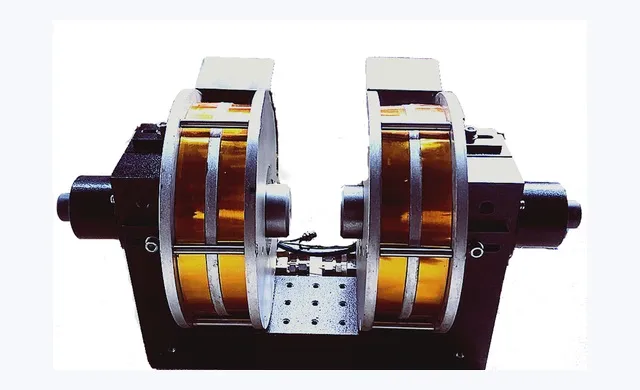 1
Field-dependent material testing
Best when: the experiment needs controlled DC or swept field exposure.
Typical modules: electromagnet, power supply, sample fixture, cooling
Confirm: field range, pole gap, sweep mode, sample size
2Sensor and calibration testing
Best when: a sensor, probe or device must be tested under defined magnetic fields.
Typical modules: electromagnet, fixture, field probe, control software
Confirm: uniformity area, positioning, repeatability, safety limits
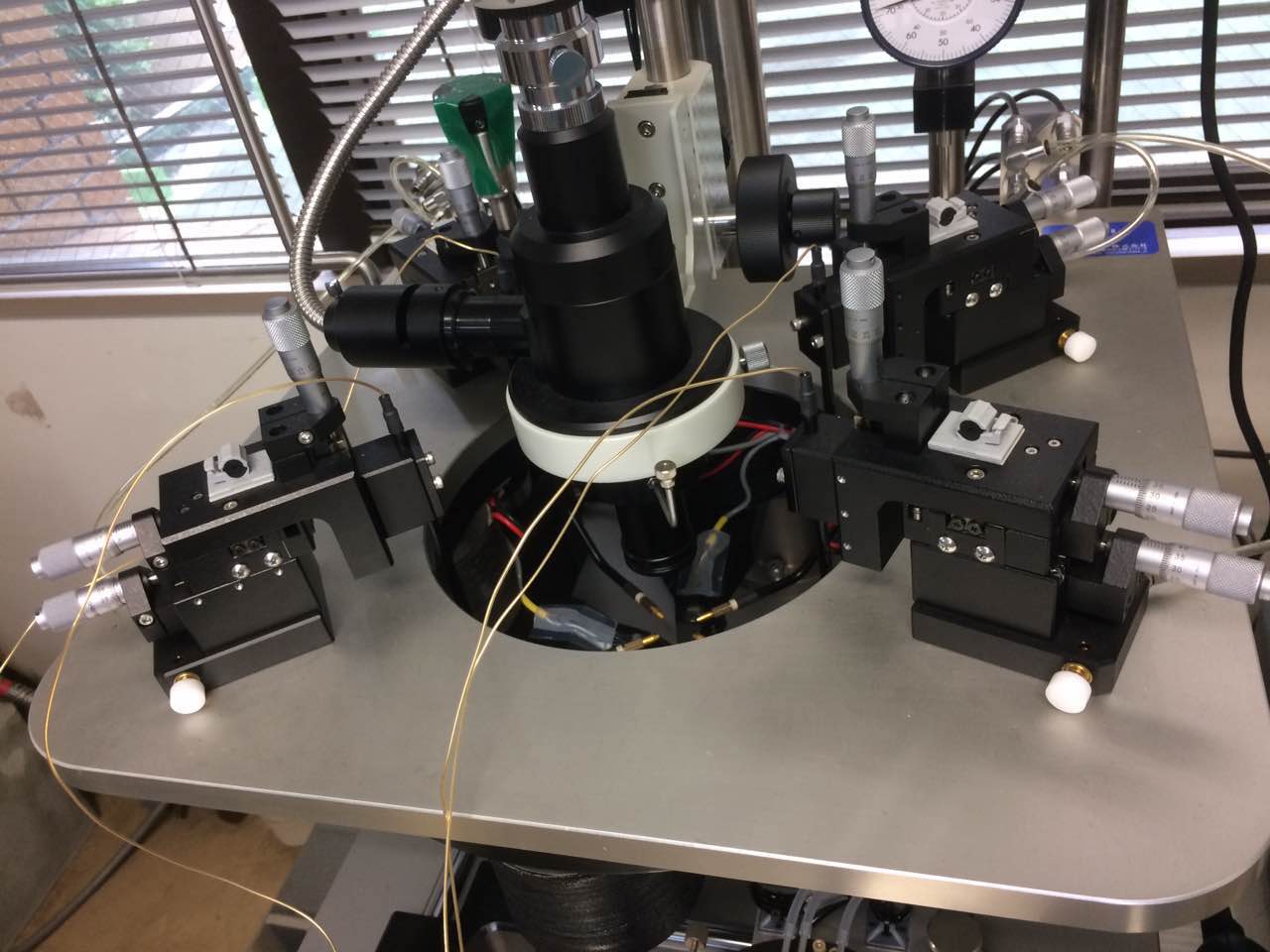 3
Hall or magnetotransport setup
Best when: magnetic-field control must be combined with electrical measurement.
Typical modules: electromagnet, power supply, sample wiring, measurement electronics
Confirm: field sweep, sample geometry, wiring path, signal quality
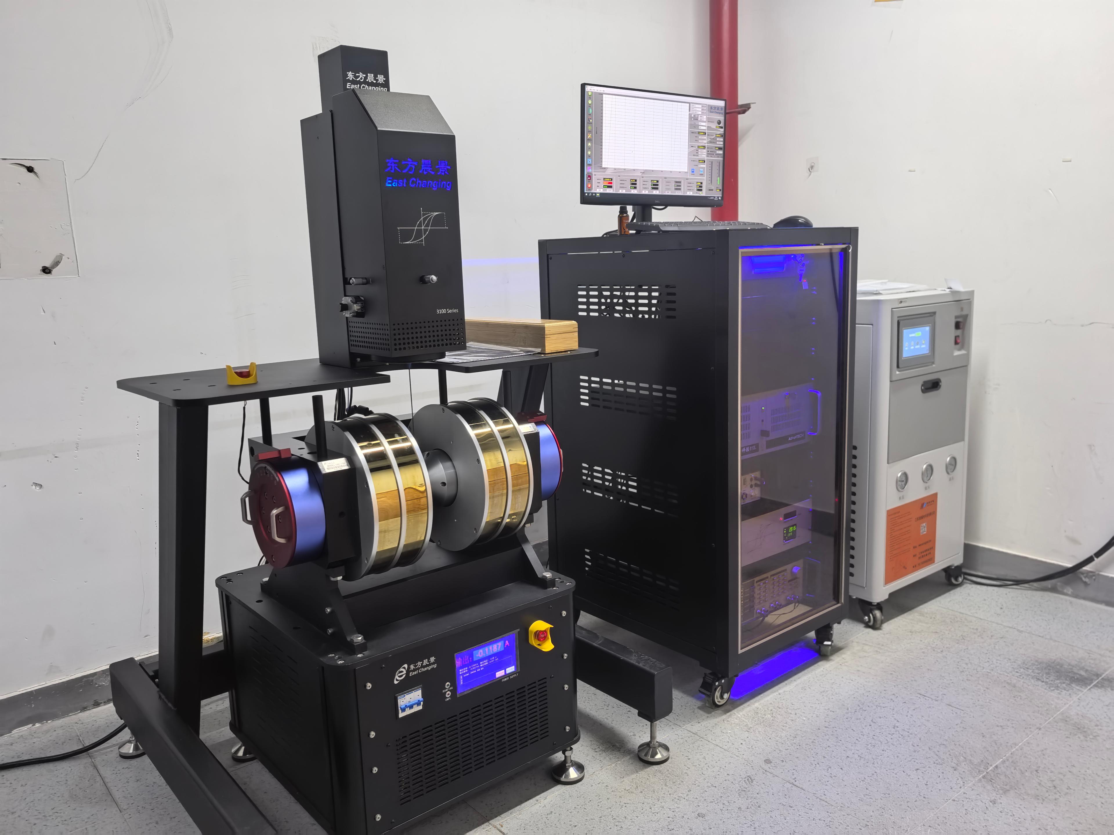 4
Industrial magnetic testing
Best when: repeatable magnetic exposure, fixture control or production-related testing is required.
Typical modules: electromagnet, fixture, safety logic, automation, data logging
Confirm: cycle mode, operating time, safety control, output data
If no path fits exactly, send the closest application goal and known system conditions for review.
Send Configuration DetailsConnect Electromagnet Systems to the Right Application Path
Electromagnets are often selected because the experiment needs controlled field exposure, field sweep, sensor response, transport behavior or repeatable magnetic testing. Use the closest application path before sending detailed conditions.
Application-system logic
The application does not define a fixed model. It helps identify which field source, power supply, sample access and measurement interfaces should be reviewed.
1Magnetic Materials Research
Measurement focus: magnetization, hysteresis, coercivity and field-dependent behavior
Electromagnet role: provides controlled DC or swept field exposure for material characterization
2Semiconductor Hall Measurement
Measurement focus: carrier type, mobility, concentration, resistivity and Hall coefficient
Electromagnet role: provides the applied field path when Hall or transport platforms require an external field source
3Magnetoresistance Measurement
Measurement focus: R-H curves, R-T curves and field-dependent transport behavior
Electromagnet role: supports field sweep, polarity control and repeatable magnetic-field exposure
 4
Industrial Magnetic Testing
Measurement focus: sensor output, magnetic response, cycle mode and repeatability
Electromagnet role: supports fixtures, safety control, automation and repeatable test workflows
If the application path is unclear, send the experiment goal and required magnetic-field conditions first.
Discuss Application-System FitConfirm Electromagnet Engineering and Test Items Before Delivery
Electromagnet testing should be linked to the agreed experiment conditions. Field behavior, power supply matching, cooling limits, sample access, safety logic and acceptance records should be reviewed before shipment or final project confirmation.
FAT logic for electromagnets
The test plan should confirm what matters for the actual field source and experiment, not only whether the equipment powers on.
Electromagnet test flow
Confirm the items that affect field output, operation stability and acceptance records.
Field verification
Covers: field strength, sweep behavior, uniformity and pole gap
Record: field test note / mapping note when required
Power and load check
Covers: current range, ripple, load matching, protection and communication
Record: power supply check / load matching review
Cooling and duty cycle
Covers: water flow, air cooling, heat load, operating time and temperature rise
Record: cooling check / operating condition note
Sample access review
Covers: working space, holder, probe clearance, wiring path and fixtures
Record: layout review / interface confirmation
Safety and control logic
Covers: interlocks, emergency stop, overcurrent, overtemperature and controlled shutdown
Record: safety checklist / operation notes
Acceptance documents
Covers: agreed FAT items, buyer notes, shipment checks and handover details
Record: FAT checklist / project-specific record
Testing note
Testing items should be agreed by project scope. Do not treat one generic checklist as proof that every experiment condition has been verified.
Send field, power, cooling, safety and acceptance requirements before final configuration review.
Discuss Testing RequirementSend the Conditions for an Electromagnet Configuration Review
A complete model number is not required. Send the known field target, pole gap, sample access, sweep mode, cooling limits, power supply needs and testing requirements so the configuration can be reviewed as one system.
Electromagnet requirement form
Use the form as a structured starting point. Unclear items can be marked for review.
Send known values
Known conditions are enough to start a configuration review. Missing items can be clarified later.
Mark uncertain limits
If field target, sample access, cooling or testing items are unclear, state that they need review.
Attach useful files
Drawings, sample photos, fixture sketches, existing model information or test notes can reduce back-and-forth.
Expect technical questions
The first response may ask for field, power, cooling or interface details before quotation.
Start with project conditions. The electromagnet route can be reviewed before a fixed model is selected.
Send Electromagnet Requirement