
Hall Effect Measurement Systems for Carrier and Transport Data
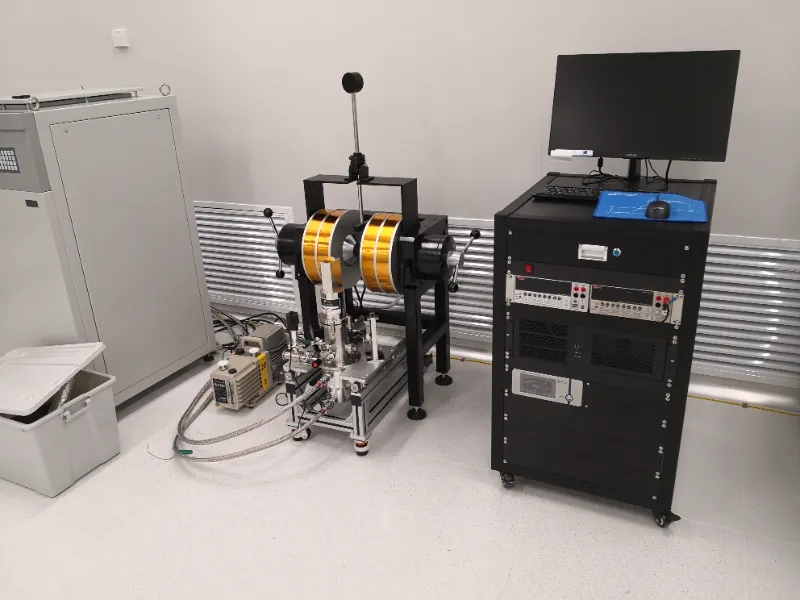
Measure carrier type, mobility, carrier concentration, resistivity and Hall coefficient with a matched magnetic field source, sample stage, electrical measurement unit and control software.
Built for projects where sample geometry, contact layout, magnetic-field conditions and low-noise signal acquisition define the quality of Hall and transport results.
Carrier data
mobility, concentration, Hall coefficient
Measurement chain
field, sample, wiring, software
Low-noise setup
Hall voltage, current, shielding
Sample and contacts
Review geometry, thickness, contact layout and wiring before choosing the measurement method.
Magnetic-field control
Match field range, polarity, sweep mode and uniformity to the required Hall or transport data.
Data and software
Capture Hall voltage, resistance curves and calculated carrier parameters with a defined workflow.
Start from the sample, target data, magnetic field range and temperature condition.
Confirm the Conditions Behind Hall Measurement
A Hall effect measurement system should be selected by target data, sample geometry, contact layout, magnetic-field conditions, temperature range and low-noise electrical measurement needs.
Target data
Confirm: carrier type, mobility, concentration, resistivity and Hall coefficient
Why it matters: The target data defines the measurement method, signal range and software calculation workflow.
Sample geometry
Confirm: wafer, thin film, bulk sample, Hall bar or Van der Pauw sample
Why it matters: Sample shape and thickness affect fixture design, contact layout and data reliability.
Contact layout
Confirm: contact position, wiring method, probe access and lead resistance
Why it matters: Poor contacts or wiring can dominate Hall voltage and resistivity results.
Magnetic field
Confirm: field range, polarity, sweep mode, uniformity and field direction
Why it matters: The magnetic field path determines Hall voltage strength, sweep behavior and repeatability.
Temperature range
Confirm: room temperature, heating, cryogenic or variable-temperature condition
Why it matters: Temperature conditions affect carrier behavior, sample access, wiring and system integration.
Current and voltage
Confirm: excitation current, Hall voltage, noise sensitivity and signal range
Why it matters: Low-level signals require suitable current sourcing, shielding and voltage measurement.
Measurement method
Confirm: DC, AC, Van der Pauw, Hall bar, resistance or magnetotransport
Why it matters: The method defines wiring sequence, field sweep logic and data-processing requirements.
Software and output
Confirm: mobility, concentration, resistivity, Hall coefficient and R-H curves
Why it matters: Software output should match the parameters and curves required for reporting or further analysis.
Send the sample type, target Hall data, magnetic field range and temperature condition first.
Build the Hall Measurement Chain Around the Sample and Data Target
A Hall effect measurement system combines magnetic-field control, sample access, electrical measurement, temperature environment, software control and calculated data output.
Magnetic field source
field range, polarity, sweep mode, uniformity
Sample stage and contacts
sample holder, probe access, wiring layout
Electrical measurement unit
current source, Hall voltage, low-noise acquisition
Temperature environment
room temperature, heating, cryogenic or vacuum interface
Control software
field sweep, data capture, calculation
Data output
mobility, concentration, resistivity, Hall coefficient
Start from the sample
Confirm sample geometry, contact layout and access limits.
Define field conditions
Set field range, polarity, sweep behavior and uniformity needs.
Match signal path
Review excitation current, Hall voltage range, noise and shielding.
Plan data output
Confirm calculated parameters, curves and software workflow.
A Hall system should be configured as a complete measurement chain, not only as a magnetic-field source.
Choose the Hall System Configuration
Different Hall effect measurement configurations support different sample formats, temperature conditions, magnetic-field paths and data workflows.
Room-Temperature Hall System
For standard Hall and resistivity measurements on semiconductors, thin films, wafers or bulk samples under controlled magnetic field conditions.
Used for: room-temperature carrier type, mobility, concentration and resistivity
Variable-Temperature Hall System
For projects that need carrier data over a defined temperature range using heating, cooling or controlled sample environments.
Used for: temperature-dependent Hall data, R-T behavior and transport studies
Low-Temperature Hall and Transport System
For cryogenic Hall, resistance and magnetotransport measurements where sample wiring, thermal contact and low-noise signals are critical.
Used for: low-temperature transport and field-dependent resistance
Electromagnet-Based Hall System
For systems that require a matched magnetic field source, stable field sweep, polarity control and integrated electrical measurement.
Used for: Hall voltage, R-H curves and repeatable field-dependent measurement
Custom Hall / Magnetotransport Platform
For special sample holders, custom contact layouts and automated Hall or magnetotransport workflows.
Used for: custom fixtures, special wiring and software automation
Configuration logic
Do not choose a Hall system only by instrument name. Start from the sample, target data, magnetic-field path, temperature condition and required data output.
Confirm before selecting
Configuration note
If the sample or contact layout is uncertain, start with the known target data and measurement environment.
If the configuration is uncertain, start from the sample, target Hall data and temperature condition.
Engineering Checks for Hall Measurement Systems
Testing should confirm the measurement chain behind Hall data, including sample contacts, magnetic-field control, low-noise electrical signals, temperature conditions and software output.
Hall measurement test flow
Project conditions define which signal, field and data behaviors should be checked.
Sample
geometry, contacts
Field
range, sweep
Signal
Hall voltage, noise
Temperature
stability, access
Data
calculation, curves
Sample and contact review
Covers: sample geometry, thickness, contact layout, probe access and wiring path
Record: sample fixture / contact layout note
Field and sweep verification
Covers: field range, polarity, sweep mode, uniformity and field direction
Record: field condition / sweep verification note
Electrical signal check
Covers: excitation current, Hall voltage, offset, noise and shielding
Record: signal check / low-noise setup note
Temperature condition check
Covers: room-temperature, heating, cryogenic or variable-temperature condition
Record: temperature condition / sample access note
Software calculation review
Covers: mobility, concentration, resistivity, Hall coefficient and R-H curves
Record: data output / calculation workflow note
Acceptance record
Covers: wiring notes, field settings, test method, data output and handover details
Record: configuration record / test note
Send the sample layout, target Hall data, field range and temperature condition before the test plan is defined.
Send Your Hall Measurement Requirement
Share the target Hall data, sample geometry, contact layout, magnetic-field range, temperature condition and measurement method so the system can be reviewed as a complete measurement chain.
Start with known measurement conditions.
A useful inquiry does not need every detail, but it should identify the target data, sample format, field condition and signal requirements clearly enough for engineering review.
Minimum starting point
Target data, sample type, contact layout, field range, temperature condition and measurement method.
What to send first
After submission
Engineering review
Check the measurement route against sample, field, signal and temperature conditions.
Configuration direction
Clarify room-temperature, variable-temperature, low-temperature or custom transport path.
Next discussion
Review missing values before quotation, detailed design or test planning.
Ready to review a Hall measurement system for your sample and target data?